
FUTURE PATCH - Intelligent Patch-Management System
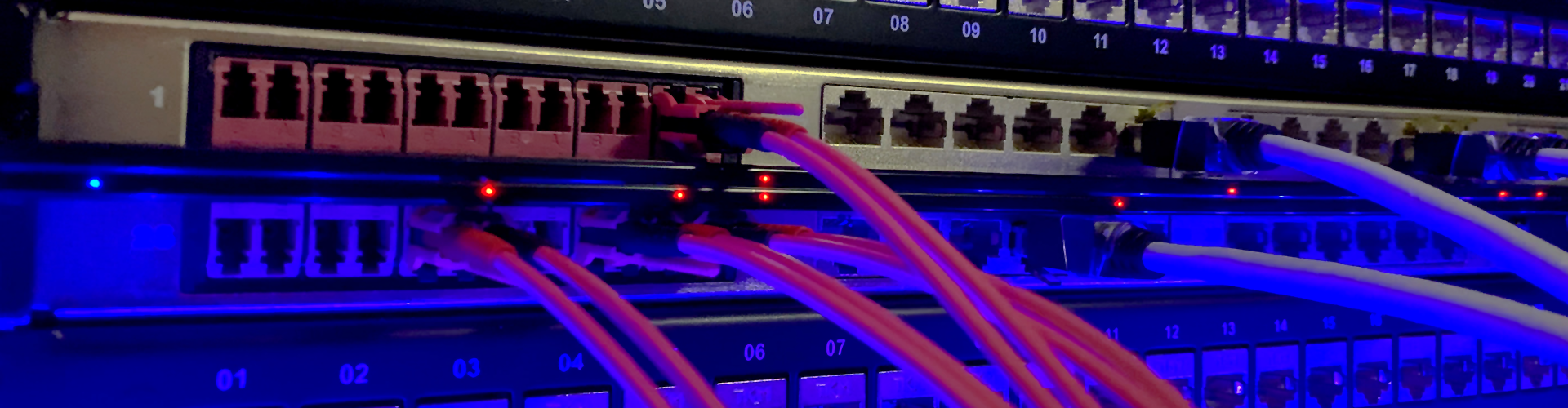
 – GENERATION 3
Electronics for retrofitting – Automatically record digital cable ID
AIM - Automated Infrastructure Management
Intelligent patching and real-time monitoring with FUTURE-PATCH for patch panels in large networks
Automated management and administration of network infrastructure is becoming important more and more. Unwanted situations can only be minimised by keeping uniform and standardised processes - optimally they are additionally automated. According to a study by Gartner, the root cause for about 30% of all network failures can be found in the cabling or the physical connection.
In order to contribute improving this situation, we offer an intelligent system that monitors the connection of the physical network layer. The area of high port density, e.g. in the network racks in data centers is the point where the solution comes in. We recommend to equip the entire patch panels with intelligent electronic and use intelligent patch cords in order to keep an eye on the real-time monitoring of the port states. A PCU (Panel Control Unit) is equipped at the front of the patch panels and scans the area in front of each port. If a connector of an intelligent patch cord is now connected with the patch panels port, the cable ID is recognized. The second side of the patch cord has the same cable ID and when the cable ID is now detected on both ports, the cable link is automatically recognized and also documented in the DCIM (Data Centre Infrastructure Management) software. If the actual state in front of a patch panel changes (e.g. based on the removal of an intelligent patch cord) and the target state (last authorised state in the DCIM software) describes something different, a warning report is automatically been published.
The system is designed for any network size, whether for 1,000 or 100,000 ports
Push notifications are sent automatically - Intelligent detection of cable types
Real-time monitoring of the physical connection with simultaneous documentation

Automatic recording of all "Moves, Adds and Changes" and thus minimisation of errors in the documentation
Network Security - Reliability - Uptime
In order to meet the ever-increasing demands for fail-safety and reliability, the basis of an entire network must be able to exchange data safely and error-free at all times. To ensure this, the physical network layer must always and without exception be reliably connected correctly. This can often only be achieved through standardized processes that automatically detect changes and also document them correctly in the long term. Immediate alerts to mobile devices in the situation of unauthorised changes ensure that recovery times are minimised.
When planning changes, it is invaluable if the basis of the planning (target state) - the documentation - also corresponds exactly to the real cabling (actual state). In this way, situations can be avoided right from the start where technicians on site have to make enquiries to the IT administration because their change orders cannot be carried out, e.g. because the new port to be connected to is not free and the risk is too high to remove the unexpectedly existing patch cord because it is not clear what will happen then - there is no documentation about it. In the best case, a time-consuming and costly investigation for the cause begins.
To meet the high demands of today and the even greater demands of tomorrow, we recommend investing in an AIM system such as FUTURE-PATCH, because at the end of the day this saves time and money.
How does FUTURE-PATCH work as part of a DCIM solution?
One component of a DCIM solution is the management of the physical network layer. This is where FUTURE-PATCH comes in and enables complete monitoring of the patching area in network racks. The real-time monitoring of all actual port states is realised by intelligent electronics placed on the front of the patch panels. The database of the DCIM software shows the target state in each case - if there is a difference between the two states, a message is generated in real time and the point of failure can be determined immediately. The unique advantage of such a solution is the knowledge of all states at the patch panel ports of the entire physical layer in the network. According to the Gartner study, where 30% of all network failures are due to the cabling or physical connections, this root cause of failure can be minimised.
FUTURE-PATCH is therefore an intelligent, electronics based solution that allows technicians to be visually guided (LED) on site at the rack when adding or removing patch cords and to directly check the correctness of the work. Furthermore, it is the building block in an intelligently monitored network, which permanently monitors the physical state of the patch panel ports and immediately informs by message in case of unwanted states.
Product groups and variants
The FUTURE-PATCH system is now in its 3rd generation and offers several variants per product group in some cases.
Generation 3 - Intelligent Patch Panel System - V3
- PCU - Panel Control Unit - intelligent electronics for patch panels -
- Patch panel AIMready for retrofitting with PCU -
- iCLIPs - clip for retrofitting with RFID transponder for patch cords -
- Patch cords AIMready for retrofitting with iCLIP -
RCU - Rack Control Unit
- Rack Control Unit - 19inch - 1,0 U - with text display -
- Rack Control Unit - Compact - 0,0 U - without text display -
Bus system
- Bus cable - bus connector - bus termination - crimping tool -
DCIM - Software:
- PATCH MANAGER - Infrastructure Management Software - More ...
Advatanges
- Automatic documentation of connectivity
- Real-time monitoring
- Integration in superordinated DCIM solution
- Automatic push notification for unauthorised changes
- Retrofitting at any time with V3
- LED spot light for new connections
- LED warning light for faulty connections
Core elements generation 3 - PCUs and iCLIPs

THE LATEST GENERATION OF INTELLIGENT ELECTRONICS
The PCU is the intelligent electronics in the system and is located at the front of each patch panel. The latest generation, version 3, can be retrofitted completely from the front of a patch panel. The bus system also runs at the front and offers several advantages when installing. Version 3 is a state-of-the-art scanner system that is compatible with various types of patch panels: for single keystone technology, for the classic splice box and for state-of-the-art modular cassette technology (MPO / splice and factory made connectivity).

THE LATEST GENERATION OF RETROFITTABLE CLIP
The intelligence can be retrofitted at any time: For RJ45 patch cords (Cat. 6 and Cat. 6A), the transponder is located in a retrofittable clip, which is pushed from the rear area of a patch cord towards the connectors front. This can done also when the cord is already plugged in. With patch cords in fiber optic technology (OM5, OM4, OM3, OS2-PC and OS2-APC) the LCdx clip has a plug-in unit for retrofitting a transponder tray. In both cases, retrofitting is uncomplicated and completely tool-free possible.
PCU and AIM ready Panel - V3
All Panel Control Units and the compatible 19 inch patch panels type AIMready of generation 3 can be found directly here:


iCLIPs and AIM ready Patch Cords - V3
All intelligent clips for retrofitting equipped with transponder and the compatible patch cords of generation 3 for copper and fiber networks can be found directly here:


Core elements Rack Management
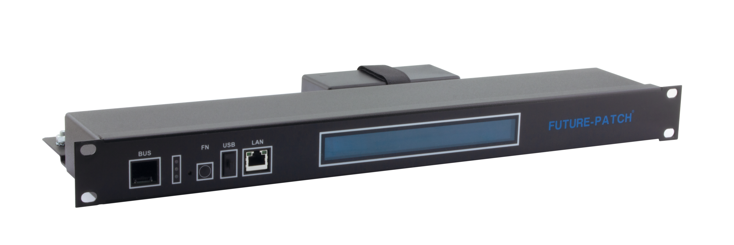
THE RACK MANAGER IN THE NETWORK
The entire system consists of a rack control unit, which is typically used per rack, and the PCUs located in this rack on its bus system. The RCU is a type of an interface - it organises the power supply and communication with the PCUs via the bus system at the lower communication level, while communication at the upper level takes place directly to a network switch via a network protocol.
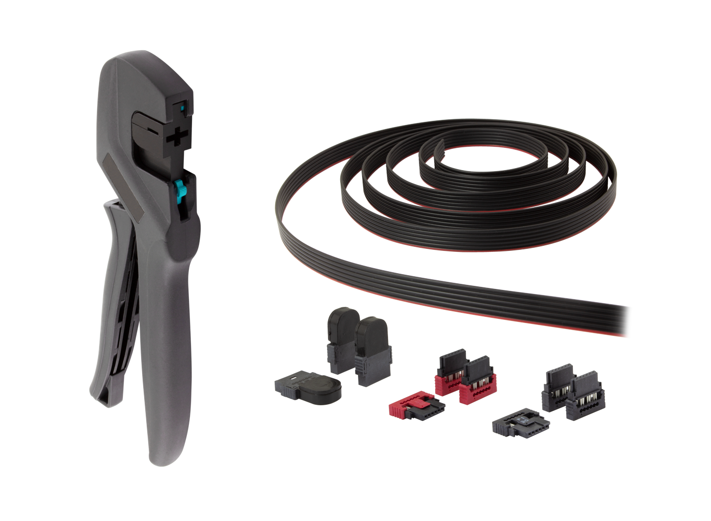
LINKING THE PCUS TO THE RCU
The bus system is the power supply and communication system of all FUTURE-PATCH products. It consists of a ribbon cable with bus terminators at both ends, and typically the RCU near one end of the cable, followed by all PCUs. A typical bus system solution within a full network rack would have the RCU at the top of the rack with all PCUs equipped on the patch panels below on the bus, which runs to the bottom of the rack.
Third party elements Management Software
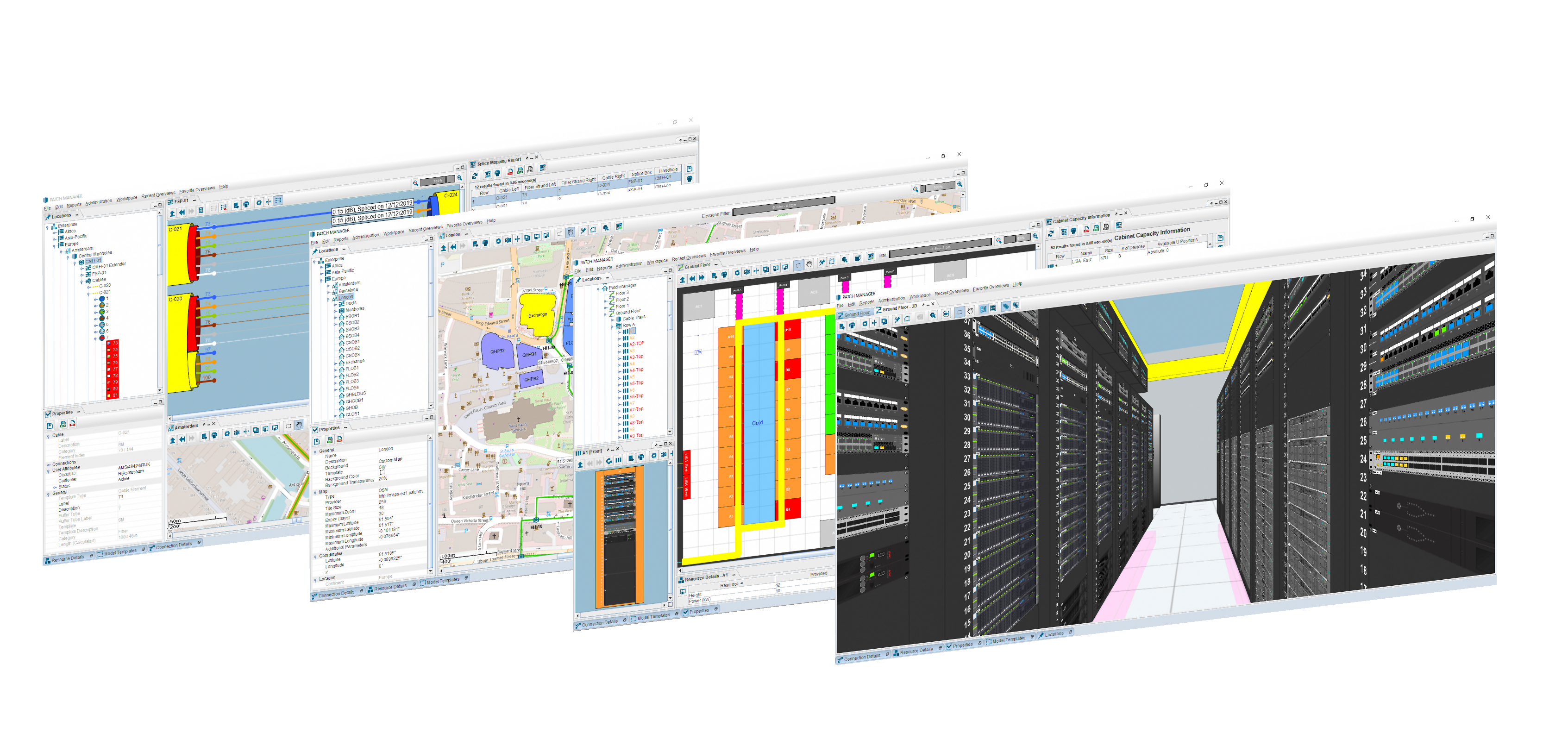
DATA CENTER INFRASTRUKTUR MANAGEMENT
A DCIM solution (Data Center Infrastructure Management) usually offers three functional blocks for the management:
1) the entire infrastructure of a data centre
2) the fiber network outside the buildings
3) the office network and building infrastructure
In particular, these include managing the hall space, free space in racks, power and climate management and the end-to-end connectivity. For fiber optic networks outside the building, it is the management of the entire physical layer including a map management with GIS (geo information system). For office networks, it includes inventory management, a work order system and the entire process for "moves, adds and changes".
-
 SKU#: 4677414-XX-PC-X Cassette System - [XXX] version - OM3 - adapters: 6x LCdx - 1x[XX] - polarity: [X]


